Map Building process
The Island generator is implemented in the engine artefact.
It is designed as a pipe and filter architecture, using a functional implementation of this architectural pattern. It leverage an algebraic geometry library (JTS) to hide the underlying mesh used to build the map.
Creating a Mesh
A map relies on a mesh, i.e., a mathematical representation of the available 2D-space to build it. A 2D-mesh contains vertices, edges binding two vertices together and faces build on top of existing edges. In the following example, we represent the different faces defined in the mesh (faces painted in black are the “boundary ones”). Each vertex depicted as a black dot is the center of a given face, i.e., its centroid. Adjacency relationships are depicted by gray lines between centers.
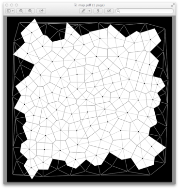
Meshes are automatically created from a set of points representing the face centers expected in the final mesh. Considering such a set of points, the MeshBuilder will automatically create vertices, edges and faces (i.e., a Voronoi diagram), as well as computing the neighborhood relation.
Set of points can also be automatically generated, using a PointGenerator. We provide in Island 3 generators, but one can extend the engine with a new one through the implementation of the PointGenerator trait.
SquaredGridgenerate a set of points aligned on a squared grid. It will generate a regular mesh using squared faces;RandomGridgenerates a set of random points. Meshes created thanks to this technique are “sharp”, leading to island that does not looks pretty;RelaxedRandomGridstarts by generating a random grid, and relax the sharpness of the previous generators by generating a voronoi diagram for this set of point, and move each point to the centroid of the associated polygon. Repeating this operation several times relax the mesh and make it more pretty.
Applying processes to enrich the map
An Island map is modeled as a mesh, plus additional properties associated to vertices, edges and faces. For example, an edge can be used by a river, a vertex can be part of the coast line, or a face can be part of a lake.
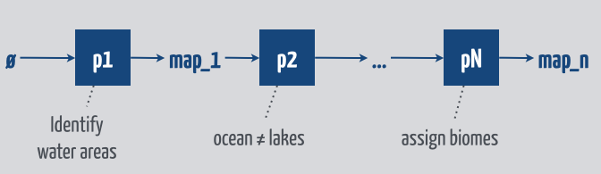
The process of building a map is defined as a pipe and filter architecture. We start with the empty map, that only contains a mesh. We apply to this map a processor p1, which produce an enriched map map_1 as output. Combining multiple processors as a sequence allows one to easily create islands.
At the implementation level, a processor is implemented as a function p: IslandMap -> IslandMap. The following figure describes a sequence of processors, starting by the identification of water areas in the map (p1), then differentiating oceans from lakes, …, and finally assigning vegetal biomes to the different faces of the map. Such a chaining is implemented with no more than classical function compositions: map_n = pN(...(p2(p1(empty_map))))
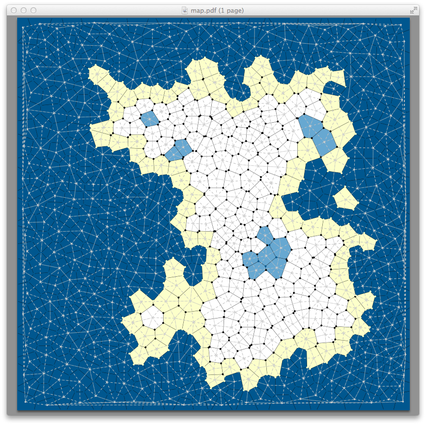
The following figure depicts a map under construction, where several processors were applied:
IdentifyBorders, marking as border faces touching the boundaries of the map;IdentifyWaterArea, using a mathematical function to decide if a face is a land or a water area;IdentifyLakesAndOcean, which annotates water area transitively connected to the borders as ocean ones (painted in dark blue), and others as inner lakes in the island (painted in light blue);IdentifyCoastLine, annotating as coast the land faces bordering the ocean (painted in light yellow).